
BMW Airhead Gearbox rebuild

If you need to do an overhaul for your airhead gearbox and going to replace new bearings and seals. Then you have come to the right place.
From the table you can see the part numbers for the needed parts, sizes and which bearings should have the seals in place and on what side.

Inside the Airhead 5 speed box
This pages below details a gearbox rebuild.
The original plan was to just replace bearings and seals and check the selector mechanism that is most common procedure for a gearbox rebuild.
This particular gearbox was an early 5 Speed transmission with optional kick start.
The kickstart part of rebuild or the replacement of some gears, is not included in this article, as most gearboxes used are without it. But if you need the details for the kickstarter and gears, please use link below to read the full version that includes them.
Tools.
There a few workshop tools which are necessary to work on the BMW gearbox. These include some circlip pliers, a strong bearing puller, a hot air gun or blow torch and a micrometer or vernier. Also useful are a shim plate to check bearing end float, a length of bar to hold the gearbox on the work bench. A wooden support plate was used to hold the gearbox on the bench without damaging the input splines. This rebuild made use of some laser cut tools but homemade versions are just as acceptable.

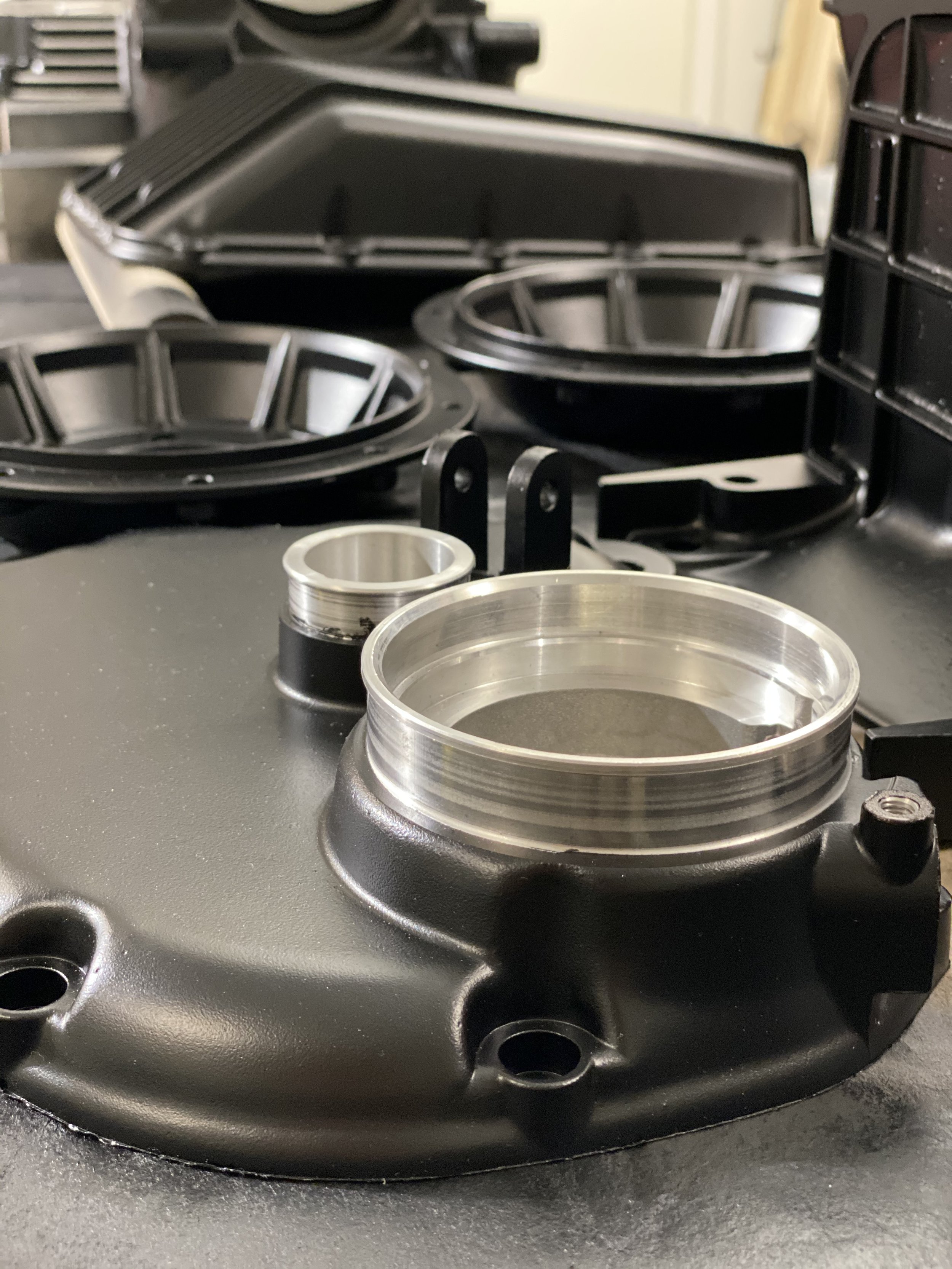
New bearings, seals, springs and gasket.
The BMW gearbox consists of 3 shafts.
Input shaft connected with splines to the clutch.
Intermediate shaft. A single assembly of gears press fitted together.
Output shaft with the flange coupling to the UJ at the top of the drive shaft.
The 3 shafts require 6 bearings.
There are up to 5 seals
Input shaft seal
Output shaft seal
Shift Lever seal
Kick start seal
Input shaft inside seal
The selector mechanism works using plate cams rather than the more comment drum selector.
To fully recondition the box a set of bearings is needed, plus the seals and the gasket for the cover.
It is also possible to rebuild the selector mechanism with new springs and circlips.

Undoing output flange nut
A 24mm socket was used to undo the centre nut on the output drive flange.
Torque on this nut is set to 220Nm, so some effort was needed to free it.
To hold the flange, a tool was made up with 4 holes for the flange bolts and an arm held in the bench vice; but a piece of angle steel with 2 holes may also be used.

Extracting output flange
Then an extractor tool was used to lift the output flange from the drive taper.
A 3 legged puller could also be used if a plate of steel is bolted to the flange to give the legs an edge to grip on.
After this
The gearbox was placed clutch side down on a simple support plate to avoid damaging the splines.
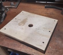
Simple wooden support plate

Undoing the end cover screws

Lifting the end cover off.
The screws were removed from the gearbox end housing and the hot air gun used to heat the box to 85degrees C.
Then a soft mallet was used to gradually lift the end cover clear.
On this gearbox with the kick start, it was necessary to rotate the kick start some, to clear the gearbox internals.

Gearbox internals with shims and oil baffle plates
With the end cover off, a note of the gearbox parts was taken.
The shims were removed taking note of their positions.
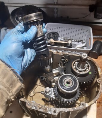
Removing the input shaft
The input shaft was lifted from the roller bearing in the housing.
Removing the selector cams
The two shouldered bolts holding the selector mechanism to the housing were undone and the selector cams removed.

1st, 2nd & 5th gear selectors
Then the 1st &2nd and 5th gear selector forks were removed by sliding the shaft out first; allowing the forks to be separated from the gear train.
To remove the two remaining gearbox shafts and the 4rd&4th selector fork, the case was heated to 100 degrees C.
With the gearbox held in the vice the parts were pulled free.

New gear shafts
The new gears came from a later gearbox and without the kick start gear.

Removing a bearing
Each of the bearings was removed using a bearing extractor/separator.
Some simple wooden jaws in the vice were used to help hold each shaft assembly safely.
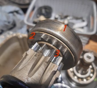
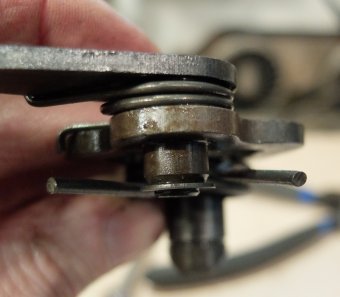
Input shaft rear bearing.
The bearing on the back of the input shaft was extracted without pulling the top-hat and bearing plate off.
1 = Bearing
2 = Bearing plate
3 = Top hat
This photo also shows significant wear on the kick starter gear.
New bearings were drifted into place on the shafts aside from the input shaft bearing at the engine end. This bearing was placed into the housing.

Bearing specifications are given in the table
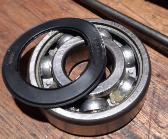
Bearing with one seal removed.
The sealed intermediate bearing was only available with both rubber shields so one was removed with a pick before fitting.
The bearing was fitted with the open side nearest the gears.
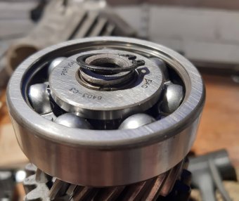
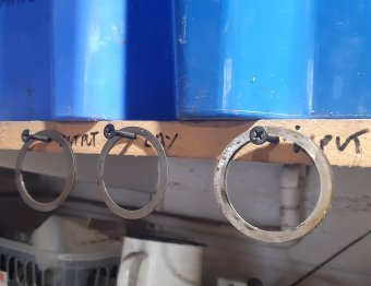
Large output shaft bearing with circlip and spring clip underneath.
The circlip issue!
There is a known issue which occurred with the introduction of the 5th gear on the /6 bikes.
The 5th gear created an axial load on the output shaft front bearing which could move the bearing forward and make the shaft motion tight.
Some bikes had a circlip to stop the shaft moving in the bearing and some didn't. Some people recommend adding the circlip if these isn't already one there.
A good description of the issue can be found on Anton's site at http://www.largiader.com/articles/circlip/
In addition, the original BMW bearing had no chamber on one side of the inner race to help the circlip work. Modern bearings don't have this so a spring ring was added to help fill the gap.
Regardless of the bike, it is worth putting some attention to this bearing to make sure the shaft doesn't move under load.
When fitting this bearing it is worth checking for free play with a feeler gauge.

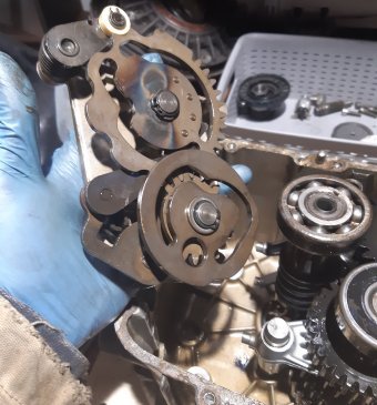
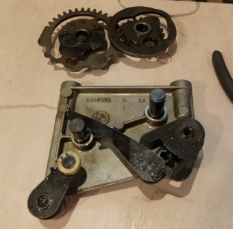
Complete selector mechanism
Selector mechanism overhaul.
To overhaul the selector mechanisms the 3 springs were replaced along with any circlips and the plastic roller was upgraded to a bearing.
The image on the right shows the selector plates set for first gear.
This is clear from the cam roller position in the let hand plate.
The tooth alignment (circled) was noted in this setting for reassembly.
Ratchet mechanism
With the pivot circlips removed the ratchet mechanism with the 3 springs was accessible.
Each lever was removed and each spring replaced in turn.

Fitting new lever plate spring.
Important to get the segment shaft spring the correct way round.
The images below should clarify.
When correctly fitted the arm will naturally sit up against the segment plate,
If the spring is not fitted correctly the arms hang down away from the segment plate and slip out of place easily. Just flip the spring over to correct this.
Spring incorrectly fitted.

Spring correctly fitted

Old and new roller (fitted)
The cam roller bearing was a direct replacement on the existing shaft.

Input shaft bearing and oil baffles
Main Gearbox Reassembly.
The man case was heated to about 100 degrees C to allow the bearings to drop into place.
The input shaft bearing was doped in and the two oil baffle plates for the intermediate and output shaft.

Intermediate shaft and gear shift fork
The 3rd / 4th gear selector fork was place on its shaft in the orientation shown, and the intermediate gear assembly was located on the fork but rotated away from the output shaft, just to start with.

First two shafts installed.
The output shaft was added to the assembly and the intermediate shaft was rotated towards it to get them to mesh.
The both shaft bearings were lowered into the housing.
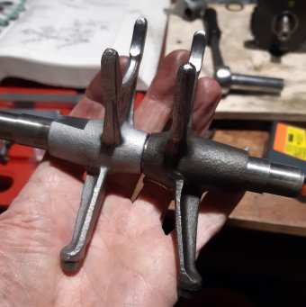
5th and 1st/2nd gear shift forks
With the remaining shift forks orientated as shown they were fitted to connect with the output shaft in the gearbox.
The flat on the 5th gear fork being at the open end of the gearbox.

Shift mechanism fitted.
The selector mechanism was set to neutral and then bolted into the gearbox, ensuring all 3 shift forks engaged in their slots on the cam plates.

Input shaft fitted
It was then possible to drop the input shaft into place.

Measuring the bearings relative to a datum plate.
Each shaft was then measured for shimming; the target to set each shaft with a maximum end float of 0.05mm.
Specification is 0.05mm.
To measure the shafts in the gearbox an 8mm plate was laser cut to create a datum and the plate was bolted into place over a new gasket to account for gasket compression..
Then the edge of each bearing was measured down to the plate surface.
In this case the DRO on the milling machine was used but a depth micrometer would also be suitable.

Measuring bearing seats in the end cover
Similarly the depth of each bearing seat was measured from the gasket surface.
The chosen shims are shown in the yellow column. This would give slightly more clearance than the specification, but better than being too tight.
0.5mm and 0.38mm shims were taken from the gearbox so just 3x 0.2mm shims were needed to make up the correct stack of parts.
The difference between the bearing pocket depth and the first bearing measurement (plus the plate thickness) was calculated to work out shimming.
However the intermediate shaft also had an oil baffle to add to the calculation.
BMW shims were available in:
0.2mm, 0.28mm, 0.38mm and 0.5mm
However, from other bearing suppliers there were also:
0.1mm, 0.2mm, 0.3mm, 0.5mm, 1mm, 1.5mm
Originally the gearbox had 3x 0.38mm shims and 2x 0.5mm shims.

Shims held with grease
The shims and the oil baffle were stuck to the bearing ends with a dab of grease.
Then the end cover was heated up and dropped into place, aligning the dowels and ensuring the gasket was flat.
A tap with a rubber mallet was needed to get it to seat.

Torquing down end cover.
The end cover was torqued down to 9 Nm

Correct orientation for output shaft seal
The shifter seal, input shaft and output shaft seals were all drifted into place with a suitable socket. The large output seal orientation was as shown and this was drifted with a piece of plastic tube.
To finish, the output flange was replaced and torqued down to a mighty 220Nm.
The input shaft was stiff to turn and so a sharp tap with a soft mallet was used to take any preload of the bearings caused by clamping the rear cover on.
Content copyrights to http://www.steves-workshop.co.uk/